Out of all the non-destructive testing techniques, only a few are suited for every type of application. For instance, on most composite materials, electromagnetic testing techniques don’t work, while computed tomography and X-rays are ideal. Likewise, ultrasounds are adaptable, but require appropriate coupling and direct contact with the surface under test, which is not possible in all cases.
What’s Liquid Penetrant Testing?
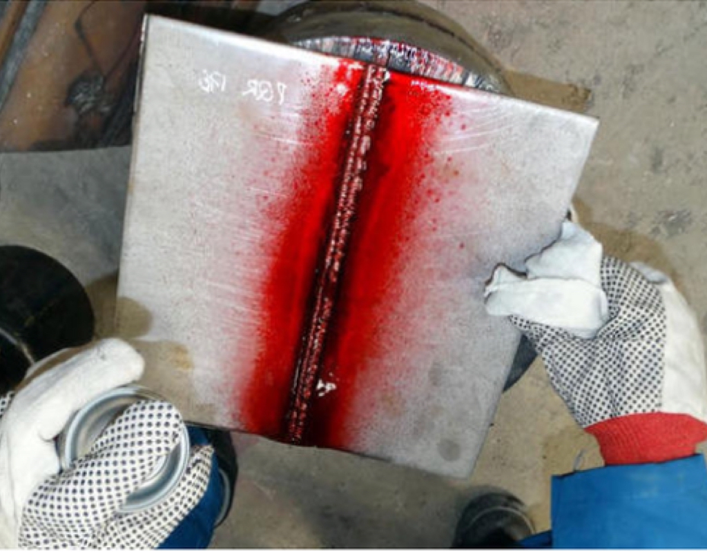
Liquid penetrant testing, also known as dye penetrant inspection (DPI) or liquid penetrant inspection (LPI) is one of the most common and affordable solution and one of the oldest, if compared to non-destructive testing challenges.
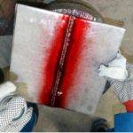
The method leverages capillary action, i.e, the ability of a liquid to flow into narrow spaces without help, even in opposition to, external forces such as gravity—to detect surface-breaking defects.
The excess is removed and a developer is applied after applying the penetrant and letting it dwell for a certain period. From surface-breaking defects, the developer draws the penetrant where it’s seeped, revealing their presence.
Advantages of LPI
Liquid penetrant testing has the following advantages:
- Works on complicated geometric shapes
- LPI materials are compact
- Sensitive to small surface interruptions
- Few material limitations such as—works on non-metallic, metallic, non-magnetic, magnetic, non-conductive and conductive materials
- Liquid penetrant testing materials are individually very cost-effective
- Visual, real-world results
Disadvantages of LPI
Liquid penetrant testing has the following disadvantages:
- Extensive, time-taking pre-cleaning critical—surface contaminants can mask defects
- Sensitive to surface-breaking defects only
- Direct connection to the surface under test necessary
- Works on relatively non-porous surface materials only
- No depth sizing
- Multi-process testing procedure
- Time-taking; post-cleaning also necessary
- No recordable data handy for progress monitoring
- User dependent
- Environmental concerns—may require disposing of chemicals and expensive handling
The biggest disadvantage is that despite lower costs and over time (cheaper materials, less training), Liquid penetrant testing is more than a screening tool; one can measure their length and locate defects, but using this method, it’s impossible to monitor the advancement of defects or determine the severity of its depth. It relegates the method to a pass/fail evaluation, that leads to discarding healthy parts and retaining unhealthy parts—which can both prove expensive.
Hence, in totality, despite the instant captivation of this cost-effective solution, it possesses various downsides that must be looked at before dismissing more progressive and more expensive inspection solutions, whether you contract inspections or perform them on your own.
Alternatives to Liquid Penetrant Testing
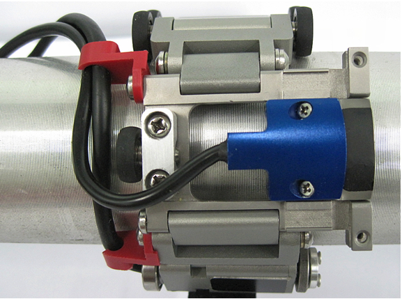
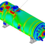
Eddy Current Array (ECA)
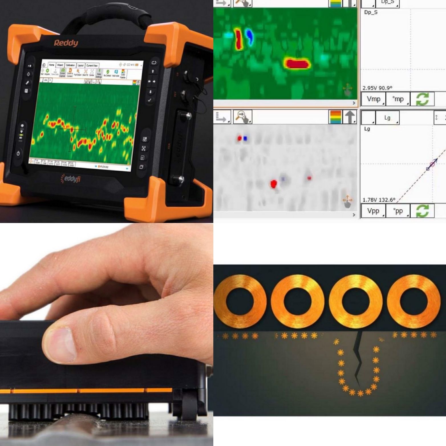
This offshoot of ECT enhances on the technology using multiplexed arrays of coils that are displayed in rows (instead of one or two coils), allowing to cover a larger area in a single scan pass. Below are the advantages of ECA:
- Eddy current array probes offer better data than manual raster scans; the larger ECA probes lowers operator dependence
- Making defect progress monitoring possible, data can be recorded.
- Wider coverage significantly results in faster scans
- The simpler ECA scan patterns makes analysis easier, quicker and accurate
- ECA offers superior detection abilities, and correct defect positioning as the inspection data can be encoded, and—perhaps—sizing.
About IRC Engineering Pvt. Ltd.
IRC is one of the fastest growing Testing and Inspection company in India. We at IRC provide Liquid Penetrant Testing, Non-Destructive Testing, Destructive Testing, Advanced NDT, Third Party Inspection, Condenser Testing, Electrical Testing, Residual Life Assessment of Power Plant, O&M Services, Fitness For Service, Civil Testing and Training services.

Recent Comments